Home/Products & Services/Integrated Continuous Gyro Survey Tool

Products & Services / Core Equipment

Integrated Continuous Gyro Survey Tool

Built for directional survey and wellbore trajectory measurement, with automatic north seeking, continuous pull-out survey capability, and coordinated operation with the surface unit and software.

Equipment Overview

A continuous gyro survey tool for complex well conditions

Core Capability

A system built from automatic north seeking to continuous pull-out trajectory survey

The integrated continuous gyro tool uses rate gyros and accelerometers as the sensing core. By measuring Earth rotation and gravity, it provides directional parameters without requiring initial surface alignment. Once local latitude is entered, the tool can perform true-north measurement and maintain true-north capability during continuous pull-out trajectory survey operations.

  • Applicable to drill pipe, casing, tubing, and open-hole trajectory survey jobs
  • Suitable for sidetracks, oriented perforation, and magnetically disturbed wells
  • Works as part of an operating system with the surface unit, GYRO software, and field support
0~60°
Inclination range
±1.5°
Azimuth accuracy
20-30 m/min
Maximum continuous survey speed range
100 MPa
Pressure boundary for the downhole tool and housing

Tool String

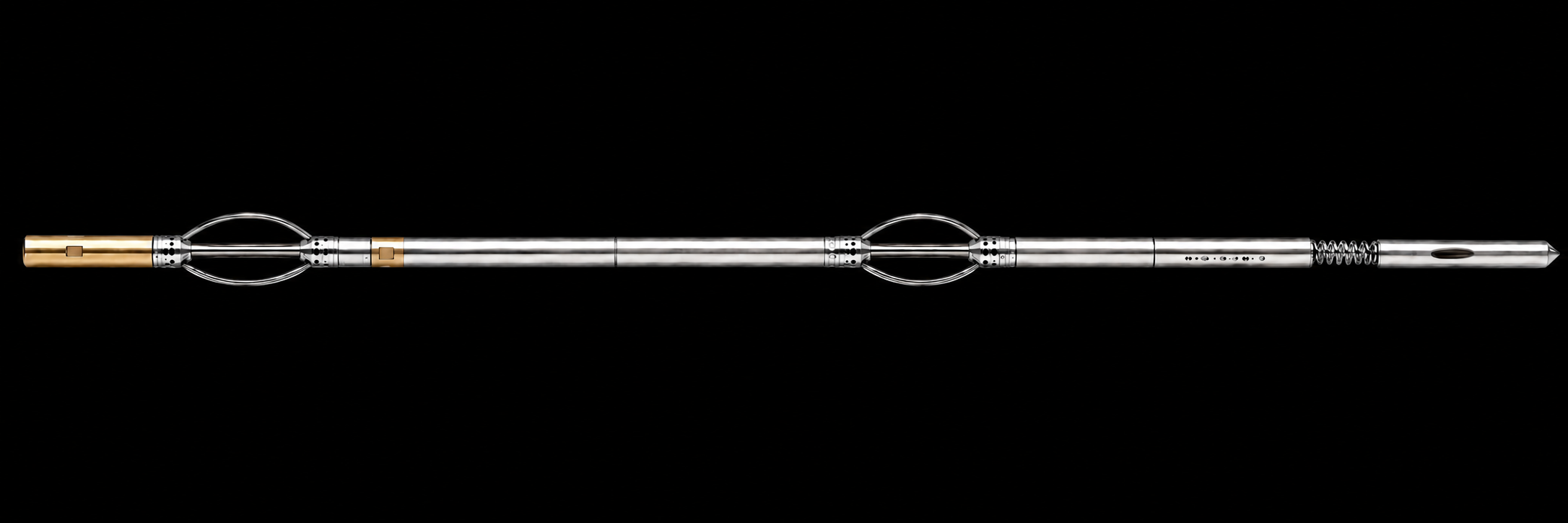
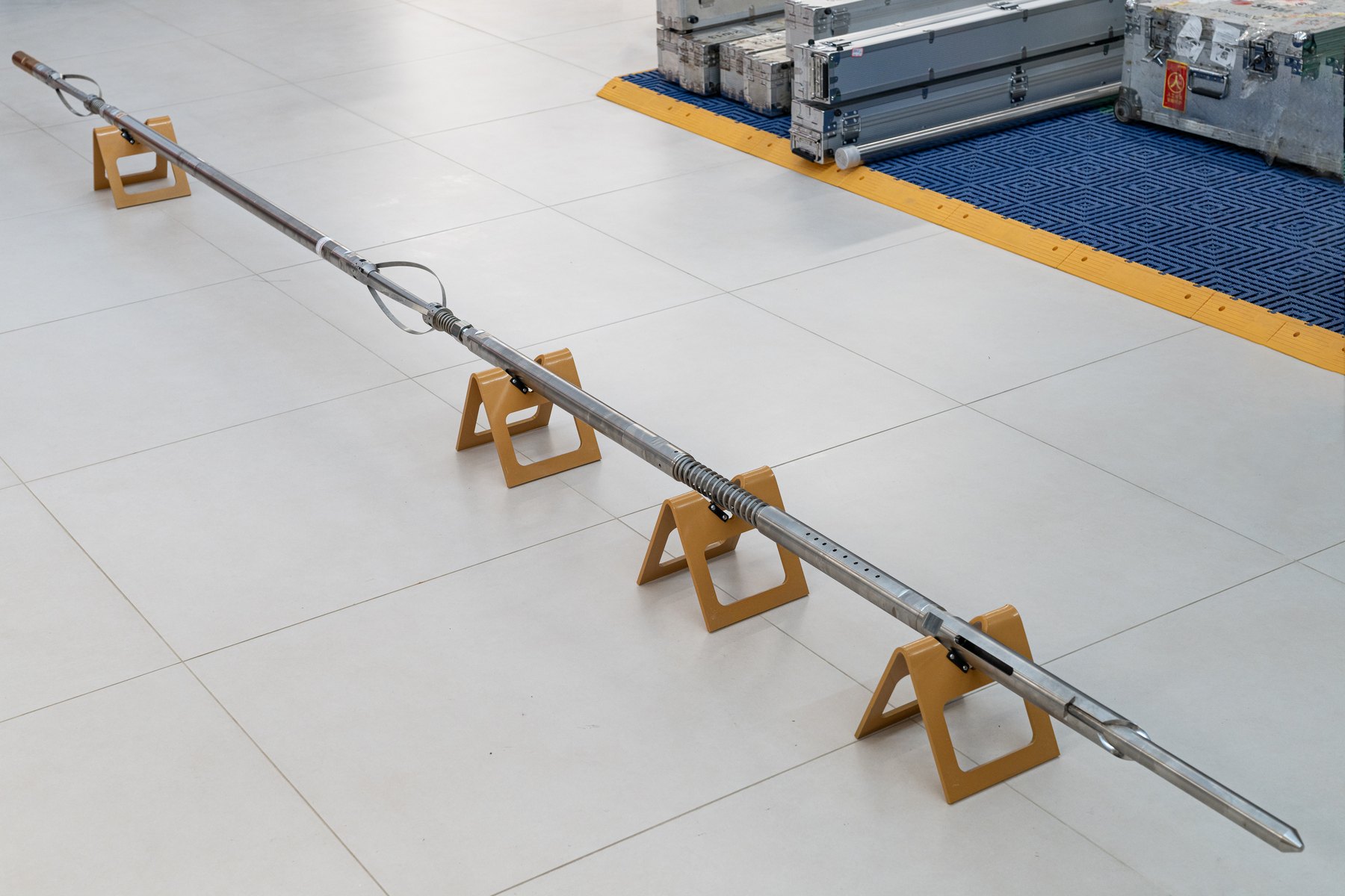
Integrated continuous gyro survey tool string

Adapters, centralizers, the survey tool, weight bar, shock absorber, and guide shoe work together as a complete tool string for stable continuous survey operations.
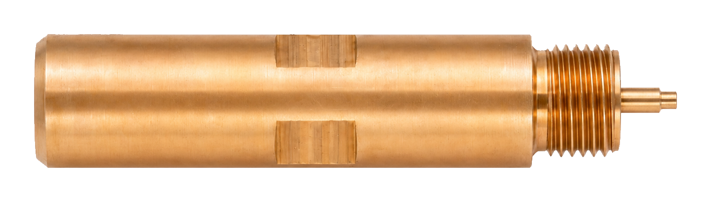
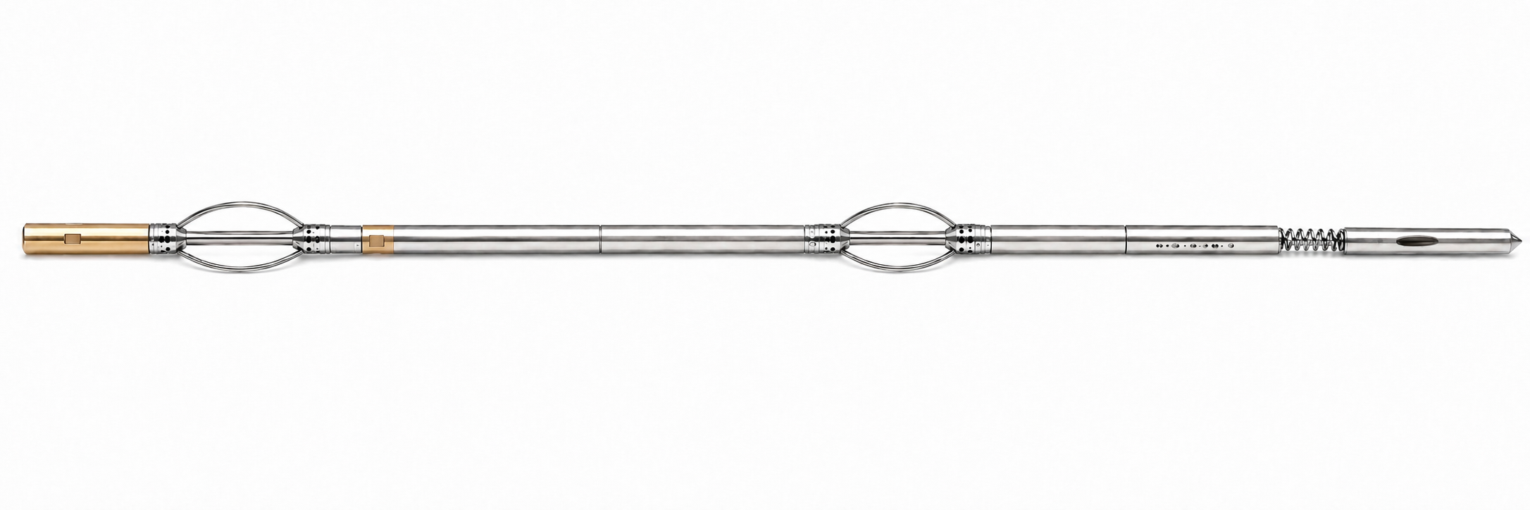
Integrated continuous gyro survey tool string Integrated continuous gyro survey tool string

Click a numbered label or component name to open the enlarged component view. Click anywhere to return to the full tool string.
Product Diagram

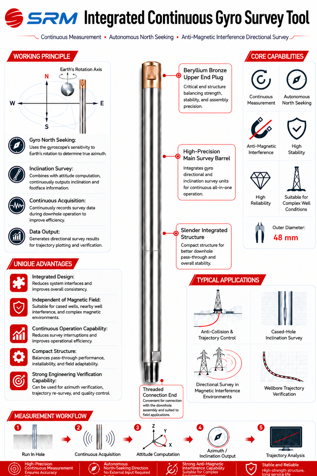
Continuous measurement, autonomous north seeking, and anti-magnetic capability

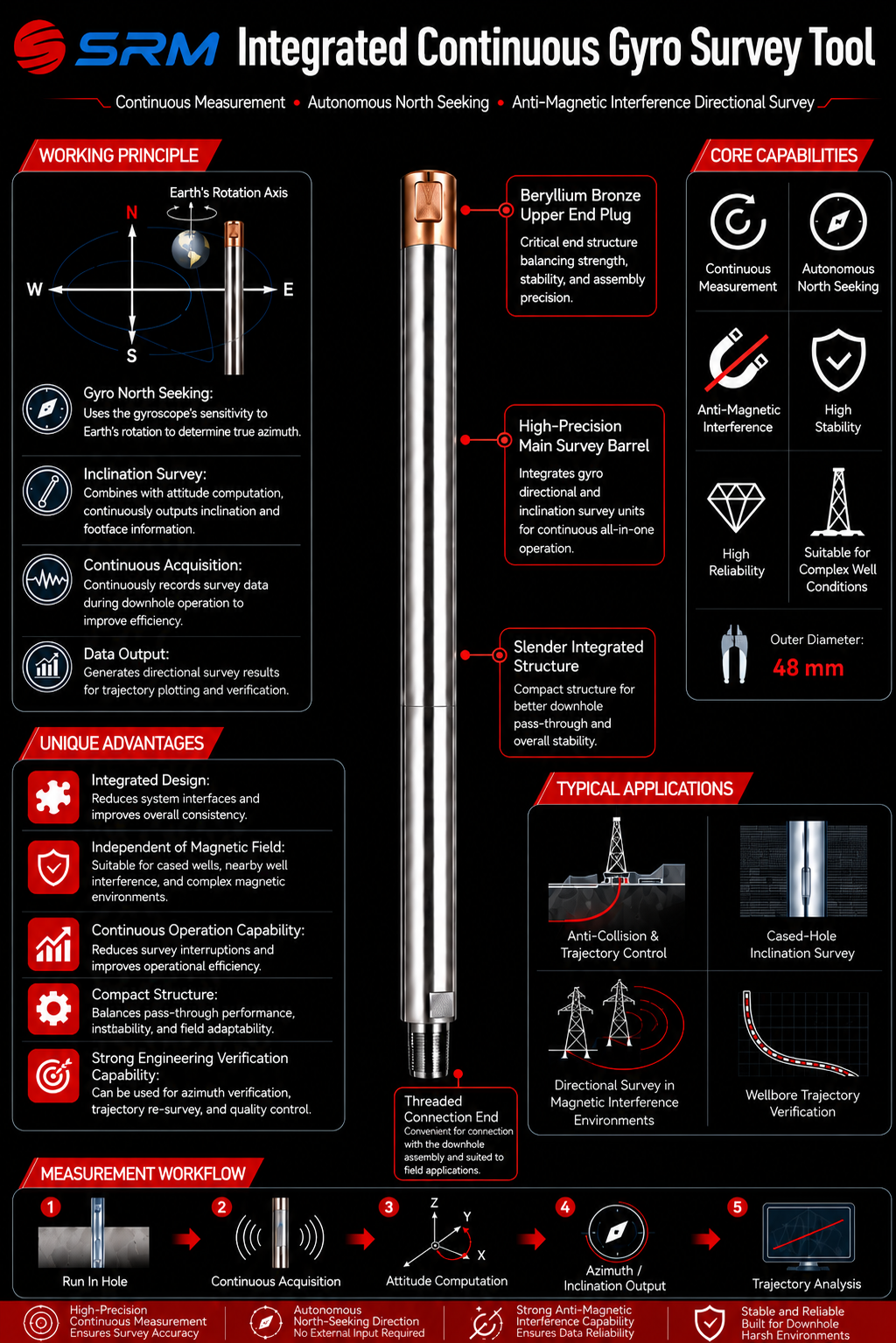
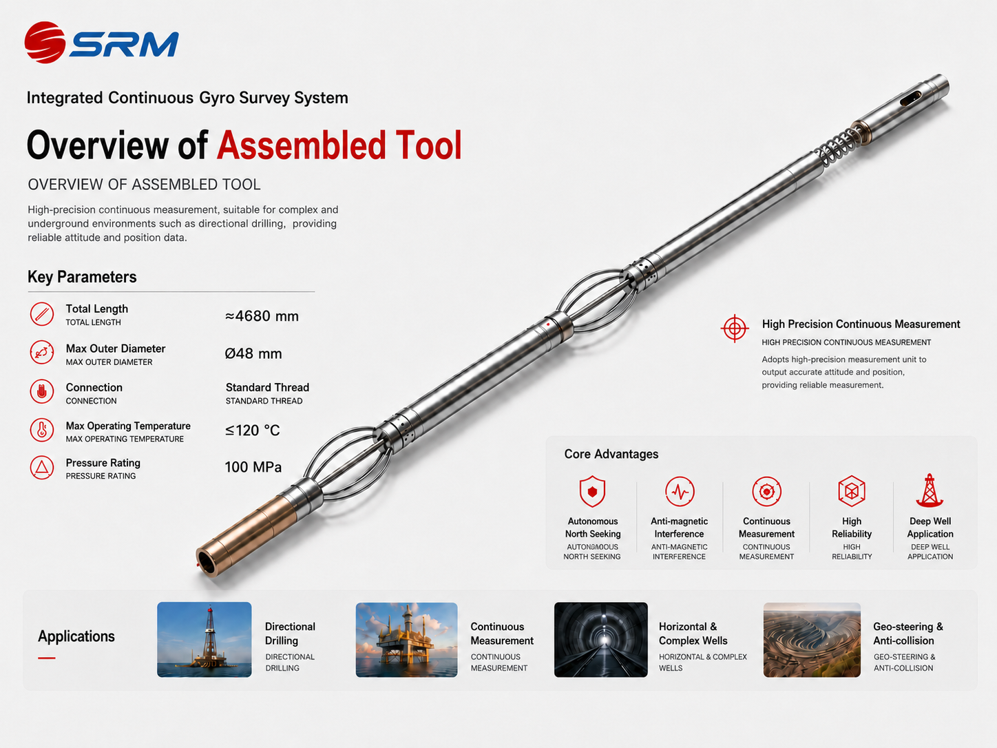
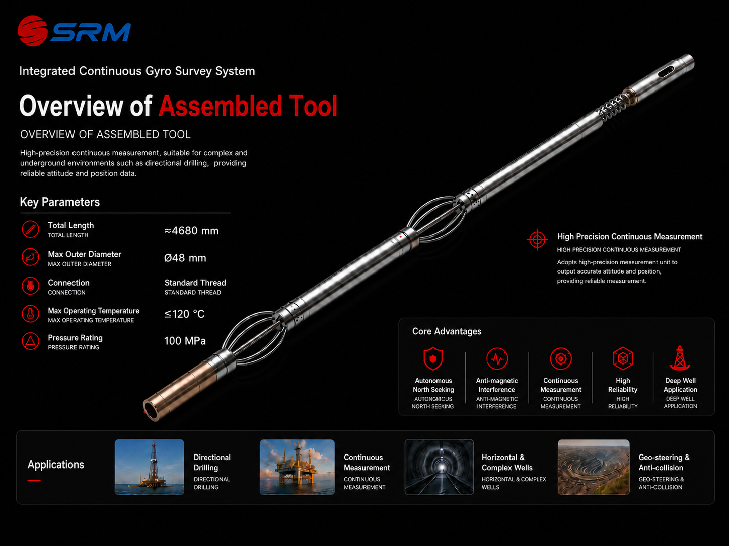
A visual summary of the tool principle, core capabilities, structural features, typical applications, and measurement workflow.

Integrated continuous gyro survey tool poster Integrated continuous gyro survey tool poster
Integrated continuous gyro survey tool product diagram Integrated continuous gyro survey tool product diagram

Technical Parameters

Public specifications and operating boundaries

Measurement Capability

Disclosed measurement parameters

  • Measurement range: inclination 0~60°, azimuth 0~360°, toolface 0~360°
  • Measurement accuracy: inclination ±0.2°, azimuth ±1.5°
  • Toolface accuracy: gravity toolface ±0.3°, gyro toolface ±2°
  • Maximum continuous survey speed: 20-30 m/min, with 20 m/min preferred

Deployment Conditions

Equipment and environmental limits

  • Tool OD: 48 mm including the protective housing and thermal flask
  • Downhole temperature limit: ≤120°C; surface unit operating temperature: -20°C to 70°C
  • Pressure rating: 100 MPa for the downhole tool and protective housing
  • Cable compatibility: single-core or 7-core armored cable up to 7000 m with resistance below 230Ω
  • Power boundary: 225 mA @120 V cable supply, 27 W maximum power consumption, 220 VAC surface power input

Applications

Application scenarios and delivery support

Offshore

Offshore platform survey operations

Covers offshore deployment, deck checks, pre-run preparation, and continuous survey execution.

Complex Conditions

Magnetically disturbed well conditions

Suitable for cased wells, sidetracks, oriented perforation, and other directional applications under magnetic interference.

Delivery Support

Surface unit, software, and training coordination

The tool is supported by the surface unit, GYRO software, delivery training, and field technical support.

Image Gallery

Gyro Survey Product Images

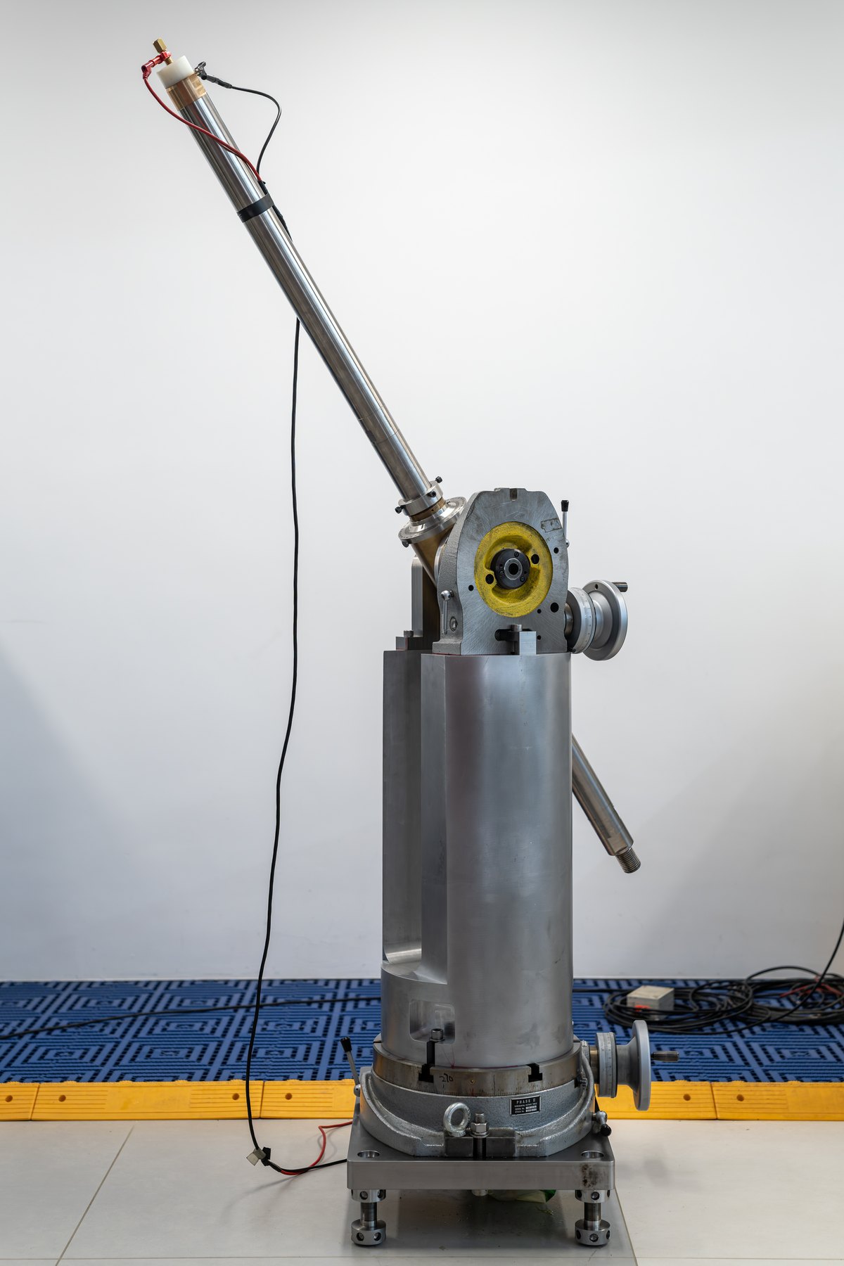
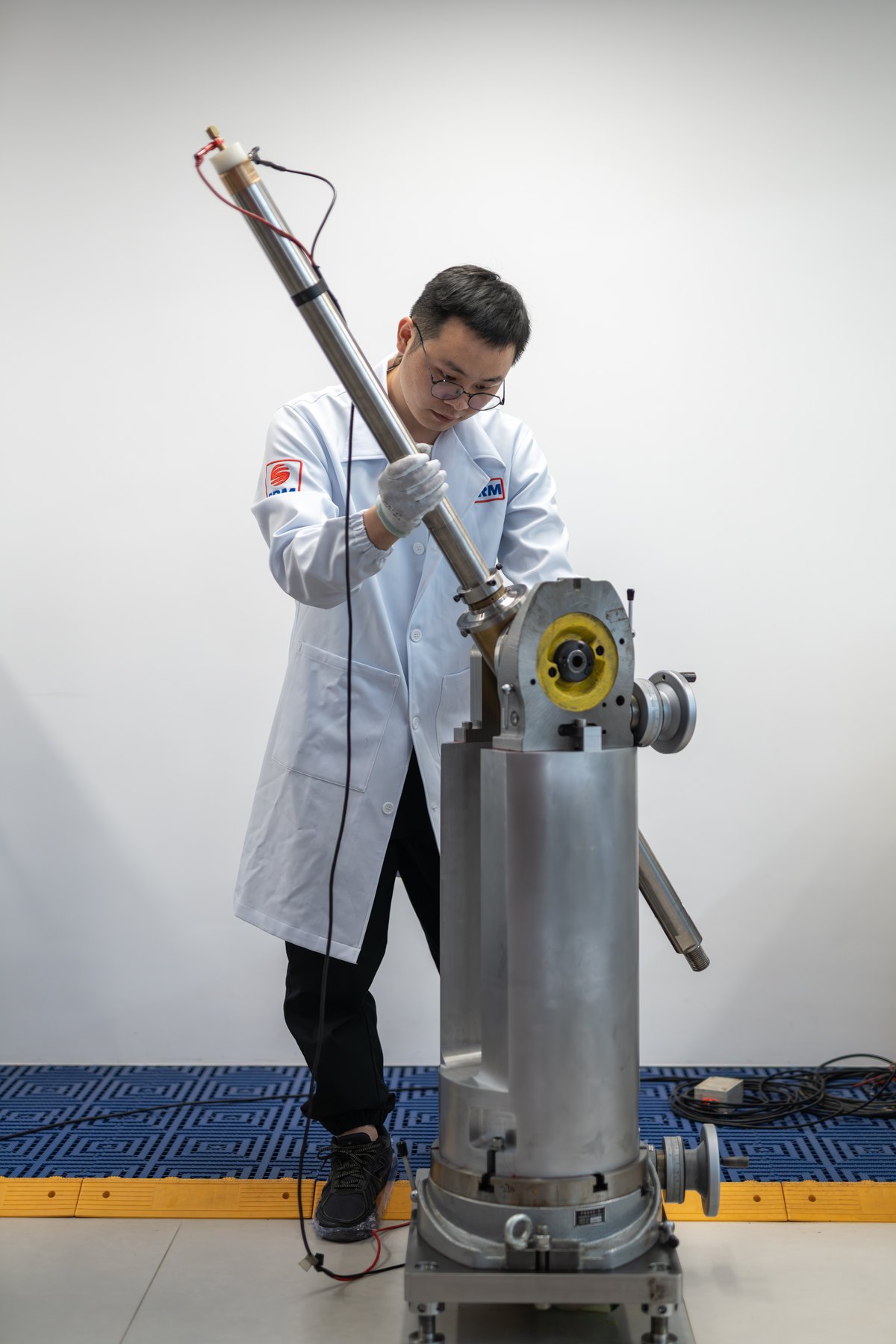
Views of the integrated continuous gyro survey tool, north-seeking operation, and calibration verification scenes.

Operation scene for the integrated continuous gyro survey tool.
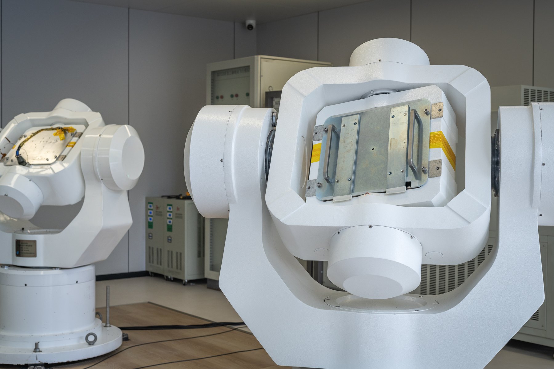
Gyro north-seeking and turntable calibration environment.
Gyro north-seeking operation and equipment commissioning.
Gyro north-seeking equipment and calibration operation.
Field operation detail of the integrated continuous gyro survey tool.
Integrated continuous gyro survey tool full-unit view.
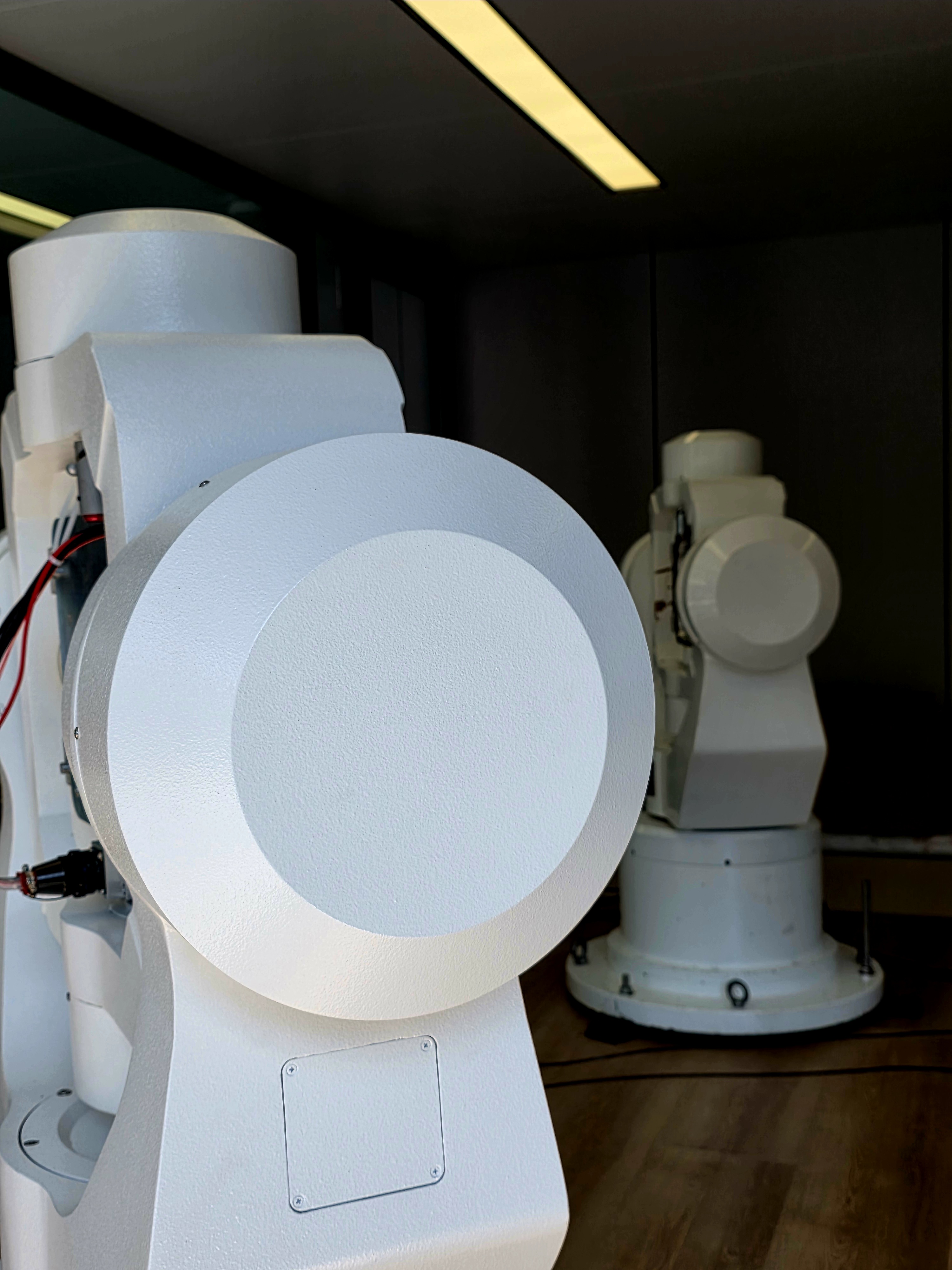
Motorized three-axis turntable for gyro attitude verification and calibration support.

Material Request

Related materials

[CN] Integrated Continuous Gyro Survey Tool Operation ManualChinese operation manual for tool operation, deployment, measurement workflow, and field use.
Submit Request
[EN] Integrated Continuous Gyro Survey Tool Operation ManualEnglish operation manual for the integrated continuous gyro survey tool.
Submit Request
[CN] Integrated Continuous Gyro Survey Tool Field Training SlidesChinese training slides for field training, operation teaching, and delivery support.
Submit Request

Materials are provided through an authorization workflow. The business team will follow up after confirming the use case and contact information.